Effects of Truck Impacts on Bridge Piers
- By
- Pooja |
- September 04, 2022 |
- Highway Engineering, Bridge Engineering, Building/ Structure Engineering,

Table of Contents
What is Truck Impact on the Bridge?
What is Truck Impact on the Bridge?
Highway bridges constitute essential nodes in transportation infrastructure networks, and they are subjected to a number of dangers, such as earthquakes, storms, floods, and impacts from heavy vehicles.
According to the 2016 National Bridge Inventory database, there are a total of 614,387 bridges in the United States. Quoting from the National Highway Traffic Safety Administration (NHTSA) Fatal Accident Reporting System (FARS), National Transportation Safety Board (NTSB) study noted that The NHTSA estimates approx. 1,000 trucks and buses (10,000 pounds gross weight or greater) collide with bridge structures each year.
Based on bridge failure statistics provided by the New York State Department of Transportation, depicts the relative distribution of the causes of bridge collapses in the United States between 1967 and 2006. It is found that collision, induced by vehicles, is the second largest cause of bridge failures after flooding.
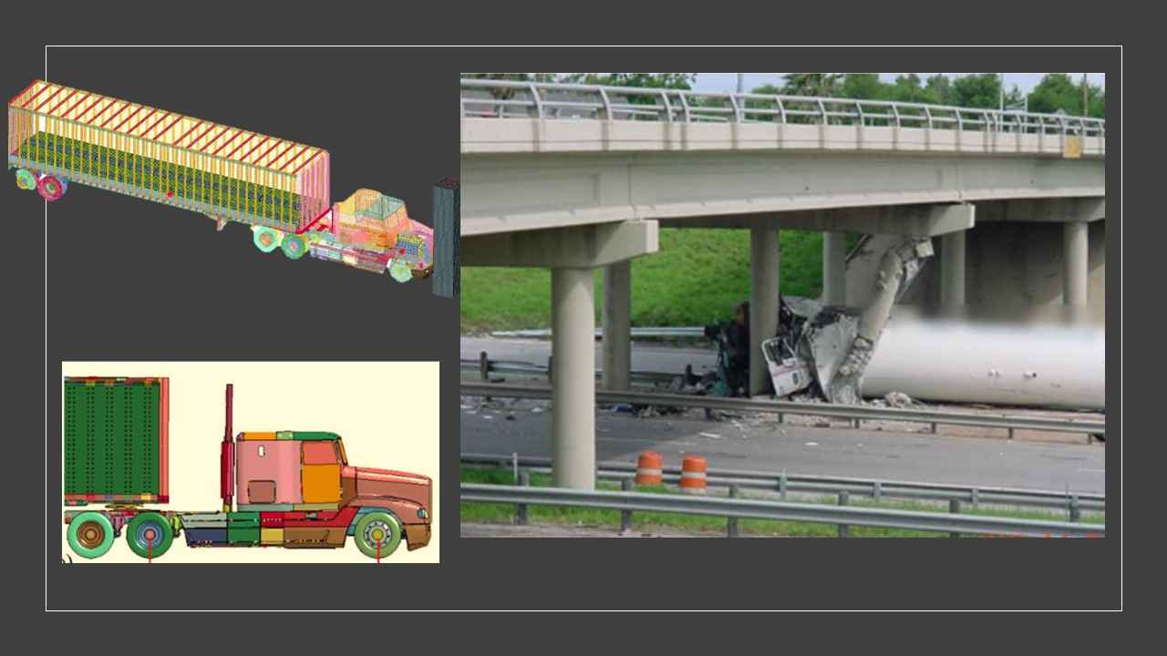
The figure below shows the force of a large vehicle on the ground In Corpus Christi, Texas, on May 14, 2004, these are the bridge piers of the Tancahua Street Bridge. The impact shattered one of the bridge's piers, although the structure as a whole remained intact.
Numerical Model
RC Pier Model
A Shanghai viaduct pier was used to create the bridge pier. Beam components were used to model steel. Each element has a mesh size of 50 mm x 50 mm.
Heavy Truck Model
The analysis was done using a heavy-duty brand of truck. It is possible to gain access to the tractor-semitrailer model, which was built to study the effects of moving vehicles on obstacles. As an example of a normal truck, like the 1991 GMC tractor pulling a 1988 Pines 14.6 m (48 ft) semitrailer, the 1979 International TranStar 4200 tractor pulling a 1977 Pullman van trailer, the 1992 Freightliner FLD120 truck pulling a 1990 Stoughton box trailer, etc. The truck mode's parts are depicted in the picture below.
There is a distinction between the original truck and the customized truck model used in the project. Despite the considerable modifications made to the truck model, several distinctions still exist between the two. The following are the most notable:
- In comparison to the test vehicle, the tractor model's wheelbase length is 400 mm (16 inches).
- There is a 28 kN (6,300 lb) reduction in curb weight compared to the test vehicle (17% less).
- Furthermore, the ballast weight is 29 kN (6,000 lb) higher than in the test car (15% higher).
According to the final two points, it's likely that the model and the real car have similar weights in total.
Read More:
In terms of vehicle technology, the tractor-semitrailer type is the most advanced due to its precise geometric details, physical functions, and material properties. During impact simulations with concrete piers, it remained stable. Additional changes were made to the FEM model to improve the simulation results.
Model Validation
Different areas of numerical model validation must be confirmed, such as the material models, types of contact between components, causes of failure of the impacted member, and hourglass control of numerical results. the model must be confirmed. This section explains how to conduct model validation. Validating material models and contact kinds is the initial stage.
Validation of Pier Model
A vehicle-piercing accident test is difficult to conduct because of experimental restrictions. Thus, in order to verify the validity of the LS-DYNA pier model, it was recommended to develop a numerical model to examine the midspan deformation and impact force time histories of the impacted beam. The results of this drop hammer impact test can be used to evaluate other numerical models. The specimen's cross-sectional area and span are both listed as 300 millimetres. The RC beam's impact point is in the middle of its span. Sliding boundary conditions were added to the other end of the experiment. A mass of 1140 kg was thrown at the midspan at a speed of 4.5 m/s to provide the impact force.
The figure shows the impact test numerical model generated in LS-DYAN. In order to model concrete and steel, it is recommended to use MAT CSCM CONCRETE and MAT PLASTIC KINEMATIC. A drop hammer and a beam use the ASTS contact type. The bond-slip effect was also taken into consideration.
The picture below suggests, If you look at the highest displacement, you can see that the difference is negligible. The impact test's maximum displacement is 31.2 millimetres, while the numerical result's maximum displacement is 31.7 millimetres, a difference of 1.6%.
The impact test's residual displacement is slightly bigger than the numerical result. “At the bottom of the damaged experimental specimen, where cracks were observed to appear, damage to the concrete is most concentrated. Material models (MATs) (CSCM CONCRETE MATs PLASTIC KINEMATIC) and contact types (ASTS) of pier models have a strong link with the deformation, impact force, and crack pattern of the model pier.
According to the impact test results and numerical results, it indicates an outstanding match.” When comparing the highest impact force of the impact test with the numerical result, there is a 6.34% difference. In line with the results of the impact test, the numbers show that the impact forces tend to get weaker over time.
It depicts the experimental specimen's crack patterns and the numerical result's distribution of concrete damage. At the bottom of the damaged experimental specimen, where cracks were observed to appear, damage to the concrete is most concentrated. Material models (MATs) (CSCM CONCRETE MATs PLASTIC KINEMATIC) and contact type (ASTS) of pier models have a strong link with the deformation, impact force, and crack pattern of the model pier.
Hope this helps you understand the effect of Effects of Truck Impacts on Bridge Piers.
Please feel free to comment and share your views.
Admin, gcelab.com
Please see our Pillar Post to know why we founded gcelab.com.
Read More:

Pooja
Founder at gcelab.com, Pooja is an Entrepreneur unlocking human potential. Working in the Principles of Lean Start-up, Pooja believes in Transparency and User Happiness the most. Pooja’s background in teaching gives her a sophisticated grasp on even the most tedious aspect of course building. She is passionate about people who believe that good is not enough.
Previous Post

