What is Traffic Signal Design?
- By
- Pooja |
- February 01, 2022 |
- Civil Engineering, Traffic Engineering,

Table of Contents
What is Traffic Signal Design?
What is a Traffic Signal Cycle Time?
Pre-determined fix signal timing and actuated signal timing
How to calculate traffic signal cycle length?
What is traffic signal phasing?
What is the relationship of Cycle Length with Queuing?
Traffic Signal Design Courses?
What is Traffic Signal Design?
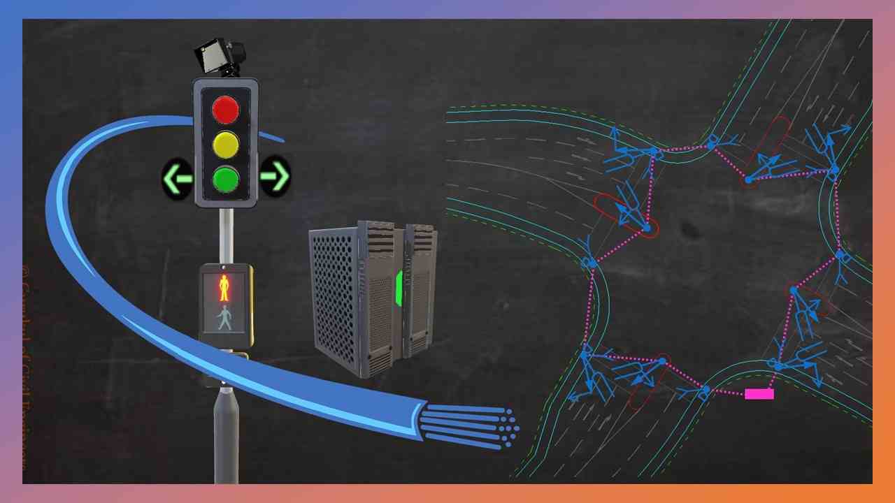
Traffic signals are used to ensure that vehicle and pedestrian traffic moves in a safe and orderly manner and to avoid long delays. Activated signalised crossings, warning flashers and beacons, pedestrian signals, fire station signals, and moveable bridge controls and warning systems are just a few examples.
Stop Time is the time it takes for a traffic signal's red light to turn on. The green interval plus the change and clearance intervals that follow it is referred to be a phase. As a result, non-conflicting movements are given to each phase within the green interval.
What is a Traffic Signal Cycle Time?
Green time
At each minor intersection, the amount of green time is distributed in a 3:2 ratio (36 seconds for the major street, 24 for the minor). Increased traffic flow enhances pedestrian safety and reduces congestion on nearby streets.
According to Forbush, a normal light cycle lasts 120 seconds, which means the longest you'll ever wait at a red signal light is ninety minutes to hundred twenty minutes. They do, however, receive reports from people who claim to have waited five minutes at a signal.
Red Time
According to Forbush, a normal light cycle lasts 120 seconds, which means the longest you'll ever sit at a red light is one and a half to two minutes. They do, however, receive reports from people who claim to have waited five minutes at a signal.
Amber Time
Find the red signal time if the amber signal time is three seconds and the green time is 25 seconds. Explanation: Total red duration is equal to the sum of green and amber times, hence total red time=25+3=28 seconds.
Pre-determined fix signal timing and actuated signal timing
Pre-timed or actuated traffic signals, or some mix of the two, are used. Pre-timed control is made up of a sequence of fixed-duration periods. The predefined green, yellow, and red intervals, when added together, produce a deterministic sequence with a specified cycle length for the junction.
How to calculate traffic signal cycle length?
Subtract the sum of the degrees of saturation for each critical phase from 1.0. The denominator is this. Round the divide to the next highest 5 seconds to get the cycle length.
The most efficient method is to employ the shortest practical cycle length that meets the traffic demand. At a signal installation, vehicles do not enter the intersection immediately. Greenshields' early research indicated that the first vehicle took 3.7 seconds to enter the intersection, with succeeding vehicles taking an average of 2.1 seconds.
Vehicles pass over an approach detector with a headway of 2 to 2.5 seconds in most cases. An average time of 2.5 seconds per car entering the intersection is a cautious number for general calculations. For planning purposes, this number can be used to estimate signal timing.
The green time plus the vehicle signal change interval for each phase are added together to get the total cycle length for all signal phases. The Highway Capacity Manual, the ITE Manual on Traffic Signal Design, and other sources have all been utilised to determine cycle lengths.
What is traffic signal phasing?
On an approach, a phase can regulate a straight-through movement and a right turn movement (in right-side driving countries). A signal phrase is specified by the MUTCD as the right-of-way, yellow shift, and red clearing cycles in a cycle that are allocated to a single or multiple traffic movements.
Split phasing is a signal design in which all vehicle movements in one direction (e.g., northbound through, right, and left) are given a green phase, followed by a phase for all movements in the opposite direction (e.g., southbound through, right, and left).
An APS that can be learned from the corresponding crosswalk at a place with split phasing delivers erroneous, unclear, and serious information. The WALK indication must only be audible from the sides of the crosswalk being signalled so that pedestrians at another crosswalk do not start crossing at the same time as vehicles are turning across their route in a protected vehicular movement”.
What is saturation flow?
The maximum rate of traffic flow is measured by saturation flow, which is an important road traffic performance metric. It is widely utilised in the control and design of signalised intersections. The number of passenger car units (PCU) in a dense flow of traffic for a certain intersection lane group is referred to as saturation flow.
One of the most important aspects of signal intersection analysis is the base saturation flow rate (BSFR). According to the 2010 Highway Capacity Manual, the default figure for base saturation flow rate is 1900 pcu/h/ln, with no local value. Its precise determination is critical in the planning and design of signalised intersections.
Read More:
- 30 Most demanding and useful design software for Civil Engineers
-
How to become a successful Transportation Engineer – 8 Key Points
What is the relationship of Cycle Length with Queuing?
The ideal cycle length for an isolated intersection corresponds to the intersection's minimal total delay. By choosing an appropriate cycle duration and green splits, this least overall delay situation can be achieved. The efficient green phases can be chosen in proportion to the critical flow ratio of the phases for a certain cycle length.
Take the derivative of the expression for a total delay of the intersection with respect to cycle length and set it to zero to get the optimal cycle length. Because the delay computations change between the Webster and HCM 2016 methods, as previously demonstrated, the ideal cycle length equation should also differ.
Traffic Signal Design Courses?
The principles utilised in traffic signal design are described in an engineering PDH course. This course covers topics such as support selection, detection design, signal head location and signal control. For making a set of traffic signal designs, a generic step-by-step approach is described.
GCELAB Online Course:
GCELAB also provides an online Traffic Signal Design course and it covers the following module in a detailed manner:
The first module includes the purpose of providing traffic signals at the junction. It includes traffic signal jargon such as acceleration lane, storage lane, pedestrian refuge area, splitter islands, signal poles, signal heads, signal hoods, inductive loop detectors, etc.
The second module offers features of Traffic Signal Phasing, Signal Cycle Time, Right Turn Phasing, etc. It also encompasses pedestrian phasing and how to organize and understand traffic signal drawings.
The third module encompasses the notion of signal timing with regard to Actuated Signal Timing and Pre-determined Fix Signal Timing. It also contains the connection of Cycle Length with Queuing and offers a detailed process of cycle Length Calculation.
It includes the detailed procedure of amber time calculation and offers a Thumb rule proposal for cycle length. Finally, it encompasses key characteristics to enhance pedestrian crossing facilities by using the newest technologies.
I hope the blog provides you with adequate knowledge of Traffic Signal Design and its associated features.
Please feel free to like, share and comment.
Admin, gcelab.com
Please see our Pillar Post to know why we founded gcelab.com.

Pooja
Founder at gcelab.com, Pooja is an Entrepreneur unlocking human potential. Working in the Principles of Lean Start-up, Pooja believes in Transparency and User Happiness the most. Pooja’s background in teaching gives her a sophisticated grasp on even the most tedious aspect of course building. She is passionate about people who believe that good is not enough.
Previous Post


